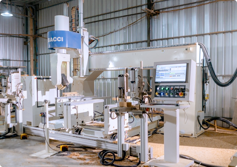
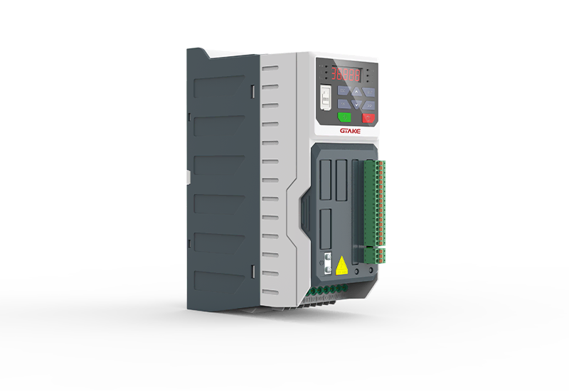
The complete electrical system consists of the CNC machine controller, AC drive/VFD, spindle motor, timer relay, braking components, and related control wiring.
AC power is connected to the input terminals (R, S, T) of the main circuit through a suitable circuit breaker. The VFD output terminals (U, V, and W) are connected to the spindle motor according to the motor wiring requirements.
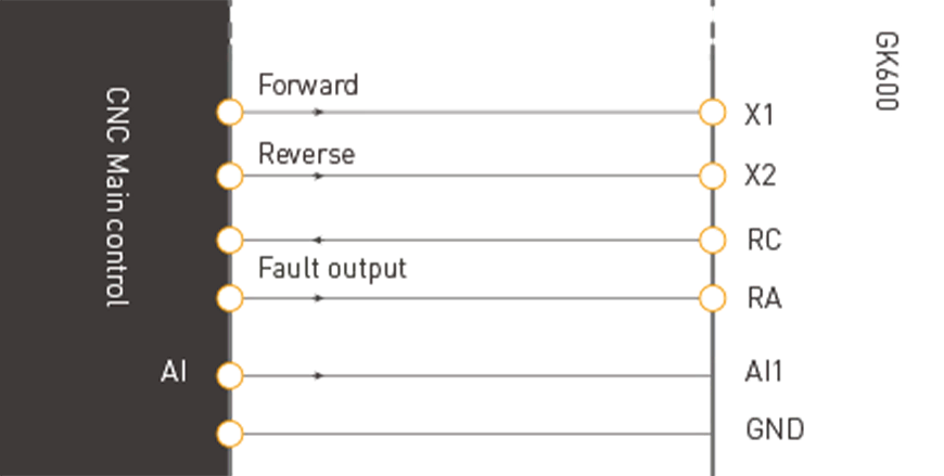
The frequency command is provided by the CNC controller through a 0–10 V or -10 V to +10 V analog signal connected to the VFD analog input and GND. This signal is used as the spindle speed reference.
Motor direction and run commands are controlled through the digital input terminals. When the forward command input X1 is activated, the spindle runs in the forward direction. When the reverse command input X2 is activated, the spindle runs in the reverse direction. When neither run command is active, the spindle remains stopped.
Two relay contacts can be used to control the forward and reverse commands from the CNC controller. At the same time, the VFD relay output can be configured as a fault output and connected to the CNC control system for drive status monitoring.
The actual terminal configuration, control logic, motor wiring, braking method, and parameter settings should be matched to the selected drive model and CNC controller. Installation and commissioning should follow the corresponding drive manual and machine wiring requirements.
How the CNC Spindle Drive System Works
The basic control flow of a CNC spindle solution is:
CNC controller → speed reference → AC drive/VFD → spindle motor → spindle
The CNC controller sends a frequency or speed command to the drive. The drive converts the command into the required motor output frequency and voltage, allowing the spindle motor to operate at the required speed.
Forward and reverse commands can be transmitted through digital inputs, while relay outputs can be used to return drive fault information to the CNC controller. This architecture allows the spindle motor control system to work as part of the complete CNC control system.
For applications requiring more advanced spindle control, an encoder and closed-loop control can be incorporated into the system. This type of architecture is more suitable when the machine requires precise spindle speed regulation, spindle orientation, synchronization, or other advanced motion functions.
How to Select a CNC Spindle Drive
Before selecting an AC drive for CNC, the following parameters should be considered:
Motor power and voltage: Match the drive to the spindle motor rated power, voltage, and current.
Spindle speed range: Confirm the required minimum and maximum spindle speed and the corresponding drive output frequency.
Torque requirements: Evaluate low-speed torque, acceleration, cutting load, and overload requirements.
Control method: Determine whether the machine requires V/f control, open-loop vector control, closed-loop vector control, or spindle servo control.
CNC interface: Check the available analog inputs, digital inputs, relay outputs, encoder interfaces, and communication protocols.
Spindle positioning: If automatic tool changing, rigid tapping, spindle orientation, or synchronization is required, determine whether encoder-based closed-loop control is necessary.