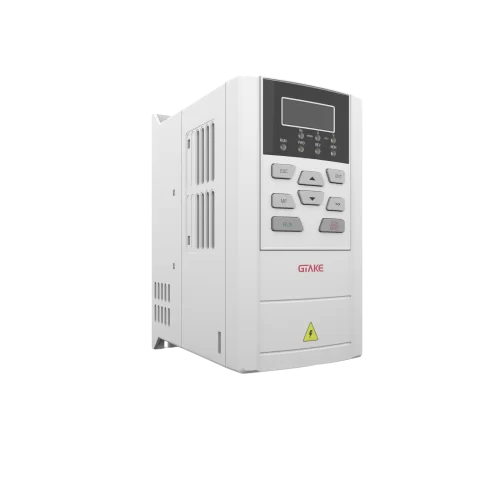
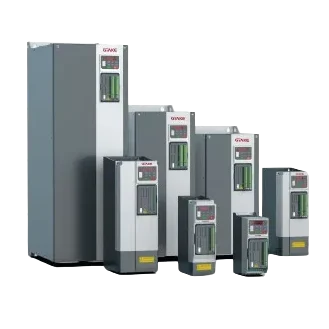
Inverters play a crucial role in modern power electronic systems, whether in electric vehicles, solar photovoltaic systems or industrial automation. However, in practical applications, inverters often encounter two common faults – overload and overcurrent. Although both phenomena may cause equipment downtime or damage, their causes, manifestations, and countermeasures are quite different. The purpose of this paper is to discuss in depth the difference between overload and overcurrent in inverters, and to provide practical prevention and solution strategies.
What is an Inverter?
An inverter is a device that converts direct current (DC) to alternating current (AC), which is widely used in different industries, such as renewable energy generation, electric vehicle drive systems and uninterruptible power supplies (UPS). Its core function is to adjust the output voltage and frequency to adapt to different load demands, thus realizing high-efficiency energy conversion.

What is Overload?
Overload refers to the state when an inverter carries a workload that exceeds its rated capacity. This condition usually involves a prolonged period of time when the power exceeds the design criteria. For example, an inverter is capable of carrying 160% of its load for one minute, which means that if the load is continuously held at 1.6 times its rated value for more than 60 seconds, the overload protection mechanism will be triggered.
What is Overcurrent?
By contrast, overcurrent is when the current momentarily and dramatically exceeds the maximum allowable operating current of the inverter. This often occurs within a very short period of time, and the current peak may reach more than ten times or more of the rated value. Typical scenarios include a current surge due to motor stalling or a short-circuit fault in the circuit.
Real-World Scenarios
Overload Example
Consider an electric vehicle climbing a steep hill for an extended period. The motor continuously draws more power than usual. Although the current doesn’t spike dramatically, the prolonged demand causes heat buildup. If this continues past the set limit, the inverter will trip due to overload.
Overcurrent Example
In an industrial setting, a robotic arm jams unexpectedly. The motor tries to push through the blockage, causing a sudden current spike. This triggers an overcurrent fault, and the inverter shuts down immediately to protect itself.
Detection and Protection Mechanisms
Overload Protection
- Monitors temperature and power usage over time.
- Uses thermal models or sensors to predict overheating.
- Implements electronic thermal protection, which adjusts based on the ratio of motor current to inverter current.
Overcurrent Protection
- Detects rapid increases in current using Hall sensors or shunt resistors.
- Triggers fast shutdown mechanisms like PWM blocking or hardware cutoff.
- May include physical fuses or circuit breakers as final safety measures.

Prevention and Response Strategies
Design Considerations
- Choose an inverter with sufficient power margin for your application.
- Ensure proper heat dissipation through cooling fans or heatsinks.
- Use smart control algorithms to manage acceleration and deceleration smoothly.
Operational Best Practices
- Regularly check wiring connections and insulation.
- Monitor operating parameters remotely using diagnostic tools.
- Adjust settings such as U/f ratio and acceleration/deceleration time if frequent trips occur.
Summary and Outlook
Although overload and overcurrent both involve excessive loads, they are fundamentally different:
- Overload relates to prolonged stress and primarily protects the motor.
- Overcurrent involves instantaneous surges and mainly safeguards the inverter.
- Correct identification of the issue helps in applying the right solution, preventing unnecessary downtime and equipment damage.
Looking ahead, advancements in wide-band gap semiconductors like SiC and GaN will enhance inverter performance. Meanwhile, intelligent protection algorithms and software-defined power systems will make future inverters smarter and more resilient.
At GTAKE, we specialize in high-performance motor drive and power conversion solutions, with a strong focus on inverter protection, reliability, and efficiency, providing complete protections for the system.
